|
|
|
|
|
|
|
|
|
|
|
|
|
|
| unit:mm |
| mit load | Metric Coarse Teeth | American Coarse Teeth | *E | W | S | B | C | D | H | F | torque | quality | ||
| Tons | Pitch | UNC | N•m | (kg) | ||||||||||
| 0.3 | M8 | 1.25 | 5/16" | 18 | 12 | 44 | 6 | 25 | 8 | 10 | 61.5 | 26 | 10 | 0.15 |
| 0.4 | M10 | 1.5 | 3/8" | 16 | 15 | 64.5 | ||||||||
| 0.75 | M12 | 1.75 | 7/16" | 14 | 18 | 52 | 8 | 30 | 10 | 11 | 76 | 32 | 10 | 0.2 |
| M14 | 2 | 1/2" | 13 | 20 | ||||||||||
| 1.5 | M16 | 2 | 5/8" | 11 | 24 | 61 | 10 | 35 | 14 | 13 | 91 | 39 | 30 | 0.35 |
| M18 | 2.5 | 一 | 一 | 40 | ||||||||||
| 2.3 | M20 | 3/4" | 10 | 30 | 70 | 12 | 40 | 16 | 15 | 108 | 47 | 70 | 0.6 | |
| M22 | 7/8" | 9 | 80 | |||||||||||
| 3.2 | M24 | 3 | 1" | 8 | 36 | 84 | 14 | 48 | 19 | 18 | 127 | 55 | 150 | 1 |
| M27 | 一 | 一 | 200 | |||||||||||
| 4.5 | M30 | 3.5 | 一 | 一 | 45 | 105 | 17 | 60 | 24 | 22.5 | 159 | 67 | 350 | 2 |
| M33 | 1-1/4" | 7 | ||||||||||||
| 7 | M36 | 4 | 1-1/2" | 6 | 54 | 126 | 22 | 72 | 29 | 27 | 195 | 85 | 410 | 3 |
| 9 | M42 | 4.5 | 1-3/4" | 4.5 | 63 | 147 | 82 | 34 | 32.5 | 225.5 | 98 | 550 | 5 | |
| 12 | M48 | 5 | 2" | 4.5 | 72 | 168 | 27 | 96 | 38 | 36 | 259 | 114 | 550 | 7.5 |
*E size thread length, can be customized.
※The information is not available, please contact the windows of CheNa districts for other dimensions.
■Side Rotating Ring Load Chart
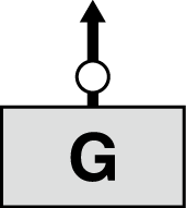
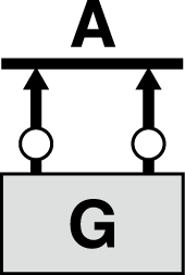
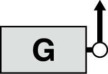
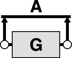
| hanging icon |
|
|
|
|
|
|
|
| hanging icon | ||
| count | 1 | 2 | 1 | 2 | 2 | 2 | 2 | 34 | 34 | 34 | count |
| load angle | 0° | 0° | 90° | 90° | 0°~45° | 45°~60° | asymmetrical | 0°~45° | 45°~60° | asymmetrical | load angle |
| M | load limit Tons | INCH | |||||||||
| M8 | 1 | 2 | 0.3 | 0.6 | 0.42 | 0.3 | 0.3 | 0.63 | 0.45 | 0.3 | 5/16 |
| M10 | 1 | 2 | 0.4 | 0.8 | 0.56 | 0.4 | 0.4 | 0.8 | 0.6 | 0.4 | 3/8 |
| M12 | 2 | 4 | 0.75 | 1.5 | 1 | 0.75 | 0.75 | 1.5 | 1.1 | 0.75 | 7/16 |
| M14 | 2 | 4 | 0.75 | 1.5 | 1 | 0.75 | 0.75 | 1.5 | 1.1 | 0.75 | 1/2 |
| M16 | 4 | 8 | 1.5 | 3 | 2.1 | 1.5 | 1.5 | 3.1 | 2.2 | 1.5 | 5/8 |
| M18 | 4 | 8 | 1.5 | 3 | 2.1 | 1.5 | 1.5 | 3.1 | 2.2 | 1.5 | 一 |
| M20 | 6 | 12 | 2.3 | 4.6 | 3.2 | 2.3 | 2.3 | 4.8 | 3.4 | 2.3 | 3/4 |
| M22 | 6 | 12 | 2.3 | 4.6 | 3.2 | 2.3 | 2.3 | 4.8 | 3.4 | 2.3 | 7/8 |
| M24 | 8 | 16 | 3.2 | 6.4 | 4.5 | 3.2 | 3.2 | 6.7 | 4.8 | 3.2 | 1 |
| M27 | 8 | 16 | 3.2 | 6.4 | 4.5 | 3.2 | 3.2 | 6.7 | 4.8 | 3.2 | 一 |
| M30 | 12 | 24 | 4.5 | 9 | 6.3 | 4.5 | 4.5 | 9.4 | 6.7 | 4.5 | 一 |
| M33 | 12 | 24 | 4.5 | 9 | 6.3 | 4.5 | 4.5 | 9.4 | 6.7 | 4.5 | 1-1/4 |
| M36 | 16 | 32 | 7 | 14 | 9.8 | 7 | 7 | 14.7 | 10.5 | 7 | 1-1/2 |
| M42 | 24 | 48 | 9 | 18 | 12.6 | 9 | 9 | 18.9 | 13.5 | 9 | 1-3/4 |
| M48 | 32 | 64 | 12 | 24 | 16.8 | 12 | 12 | 25 | 18 | 12 | 2 |
※Notice
• Equipped with a locking wrench, after locking, it is easy to install, and the lifting ring can be rotated after loosening.
• Different load directions can lift different loads, but 4 times the safety factor is guaranteed. When hoisting in the vertical direction, the working load is large.
• 100% passed the 6g go-stop gauge inspection and can be adapted to precise threaded holes.
•Complete thread specifications and wide range of rated loads can be customized according to customer requirements.
• The thread is made of alloy steel 42CrMo by precision forging, the tensile strength σb before heat treatment is 1080MPa, and the mechanical properties are improved after quenching and tempering. The surface of the lifting ring is electrostatically sprayed to improve the surface anti-corrosion ability.


